Showing posts with label Hardware. Show all posts

How to Solder

Tuesday, October 13, 2009
First a few safety precautions:
  1. Never touch the element or tip of the soldering iron. They are very hot (about 400°C) and will give you a nasty burn.
  2. Take great care to avoid touching the mains flex with the tip of the iron. The iron should have a heatproof flex for extra protection. An ordinary plastic flex will melt immediately if touched by a hot iron and there is a serious risk of burns and electric shock.
  3. Always return the soldering iron to its stand when not in use. Never put it down on your workbench, even for a moment!
  4. Work in a well-ventilated area. The smoke formed as you melt solder is mostly from the flux and quite irritating. Avoid breathing it by keeping you head to the side of, not above, your work.
  5. Wash your hands after using solder. Solder contains lead which is a poisonous metal.

If you are unlucky (or careless!) enough to burn yourself please read the First Aid section.

Preparing the soldering iron:
  1. Place the soldering iron in its stand and plug in. The iron will take a few minutes to reach its operating temperature of about 400°C.
  2. Dampen the sponge in the stand. The best way to do this is to lift it out the stand and hold it under a cold tap for a moment, then squeeze to remove excess water. It should be damp, not dripping wet.
  3. Wait a few minutes for the soldering iron to warm up. You can check if it is ready by trying to melt a little solder on the tip.
  4. Wipe the tip of the iron on the damp sponge. This will clean the tip.
  5. Melt a little solder on the tip of the iron. This is called 'tinning' and it will help the heat to flow from the iron's tip to the joint. It only needs to be done when you plug in the iron, and occasionally while soldering if you need to wipe the tip clean on the sponge.

You are now ready to start soldering:
  1. Hold the soldering iron like a pen, near the base of the handle. Imagine you are going to write your name! Remember to never touch the hot element or tip.
  2. Touch the soldering iron onto the joint to be made. Make sure it touches both the component lead and the track. Hold the tip there for a few seconds and...
  3. Feed a little solder onto the joint. It should flow smoothly onto the lead and track to form a volcano shape as shown in the diagram. Apply the solder to the joint, not the iron.
  4. Remove the solder, then the iron, while keeping the joint still. Allow the joint a few seconds to cool before you move the circuit board.
  5. Inspect the joint closely. It should look shiny and have a 'volcano' shape. If not, you will need to reheat it and feed in a little more solder. This time ensure that both the lead and track are heated fully before applying solder.


If you are unlucky (or careless!) enough to burn yourself please read the First Aid section.

Using a heat sink
Some components, such as transistors, can be damaged by heat when soldering so if you are not an expert it is wise to use a heat sink clipped to the lead between the joint and the component body. You can buy a special tool, but a standard crocodile clip works just as well and is cheaper.

Test Your PSU's Voltage Rails With A Multimeter

Saturday, September 19, 2009
The best way to get the most accurate readings from your PSU is to use a multimeter. Hardware monitors, and BIOS will not give you TRUE real voltages on those 3 main voltage lines. Many people still rely on means of software, such as MBM, Speedfan, and the BIOS, but these are all very unreliable.

More about software/bios readings on the rails:

In order for the software to read your PSU's rails, or lines of voltage required to run your computer properly, a chip on your motherboard needs to read these voltages. There is usually resistance between the PSU and the monitoring chip on the motherboard. According to a motherboard monitoring software, an 12-volt Rail can be way under spec. You want your voltage to be within 4%. So you want your 12-volt rail to be within 11.52 to 12.48 during load. This means when you are running your CPU at 100% you do not want to drop below 11.52 or you may experience stability problems including but not limited to system restarts and Windows crashes. For the 5-volt rail, you want it to be within 4.8 to 5.2 to be within the 4% range. As for the 3.3 volt rail, you want it to be within 3.17 to 3.43.

What are RAILs?

Rails are the above mentioned voltage lines coming from your PSU to your motherboard and devices in your motherboard. The 3.3-volt and 5-volt generally power the devices like the motherboard, PCI slots, AGP slot, etc. The 12-volt is usually used for things with motors like the hard drives, CD-ROM, fans, etc.

What's a multimeter / voltmeter?

A multimeter is an electronic measuring instrument that combines several functions in one unit. The most basic instruments include an ammeter, voltmeter, and ohmmeter.

A multimeter can be a handheld device useful for basic fault finding and field service work or a bench instrument which can measure to seven or eight and a half digits of accuracy. Such an instrument will commonly be found in a calibration lab and can be used to characterize resistance and voltage standards or adjust and verify the performance of multi-function calibrators.

The 1st pic is a Digital Multimeter, and the 2nd is an Analog Multimeter:


Preparations:

CAUTION: This test involves using probes with the computer ON. Please only do this if you feel competent enough to be dealing with electricity. If you short rails, you could risk damaging the PSU and possibly your components. I cannot be held responsible if something goes wrong, this is merely a guide. If you feel any concern, please post BEFORE doing this, and we will be glad to help.

If you are afraid of doing such a thing and you are not sure what any of this guide means, I encourage you to NOT do this. Electricity is dangerous and can kill you in a heartbeat. Remember this is only a thread, what informs you, on how to do this. If you aren't sure of what you doing, DON'T DO IT.

Firstly, you will have to set up the multimeter to read the voltages you will be measuring. You should be able to move a dial on the multimeter. You want to move this to the number 20 (like this), in the section which relates to DC voltage. This is usually represented by THIS symbol.
Put The Black probe into the 'COM' plug on the multimeter. The Red probe should be placed in voltage detection plug.
DO NOT insert the probe into the 'current detection' plug, which on cheaper MM's usually has a '10A max or 10ADC' Label.

More preparations:

The first thing you want to do is download Prime95. Download it here. Prime95 is used to put your system at full load. You want your system at full load when checking your voltages to ensure your PSU is up to spec. The whole point is to make sure your PSU can handle what your system asks of it. This can only be done by stressing your system during the voltage test.

Now you want to shut down your system and then open the side so you have access to your AUS and a Molex plug. How to test with the Molex plug is discussed later in the guide. Lay your computer on it's side during this test or this will be more difficult than necessary.
Locate a free 4 pin Molex Connector, although you can test the back of molex connectors, if you have non spare, it just might be a bit more akward.
Locate the AUX connector:


And pull these into an area free from any clutter, so they are accessible for the probes on your multimeter. This may be a good time to do some cable rearrangement.

Measuring the VOLTAGEs:

Time to start. You want to observe these 3 voltages in all states. So you will have to set up the probes BEFORE you turn the PC on, because you want to observe the voltages for.

* POST
* Boot
* Windows Start up
* System at Idle
* System at Load
* Shutting Down


That is the problem with most PSU measuring guides, they test the PSU externally, with only the load of maybe a few fans, which does NOT give any real kind of indication on how the PSU copes powering a computer. So, set up each of these measuring, and observe/record the voltages at each stage as listed above. Ideally, they should not go above or below the rated voltage, though no component is perfect, which is why there is an ATX specification, which sets parameters for each voltage.

It is my opinion though, that any PSU which falls close to the min ATX spec, needs replacing.
Another Purpose of these rail tests are to find out how much your rails fluctuate, and if they do a lot, even if they stay within ATX spec, id suggest replacement. Clean, Stable voltage is just as Important as enough Voltage.


STEP 1: Measuring The 12V Rail

For this you just need the 4-pin Molex. Insert the red probe into the yellow 12v connector, and the black probe into any black Ground connector on the Molex:


STEP 2: Measuring The 5V Rail

For this you just need again the 4-pin Molex. Insert the red probe into the red 5v connector, and the black probe into any black Ground connector on the molex:


STEP 3: Measuring The 3.3V Rail

For this you will need the a.> AUX Connector Only, OR b.> a combination of the AUX and 4-pin Molex.
Insert the red probe into either one of the two orange 3.3v connectors on the AUX connector
Insert the black probe into any of the black ground connectors on the AUX connector, or the 4-pin Molex connector.

Note: Some people may struggle to insert the probe into the aux connector like is pictured, but you can also test the rail via the back of the connector.

method1: Using Just AUX Connector:

method2: Using AUX and 4-pin Molex:


Another way of testing this is in the DriverHeaven's Guide, their method is involving the 20pin Motherboard plug and a Molex Plug.

method3: Using 20pin plug:


More info about using the 20pin method, relating that you can measure the 3.3v,5v,12v from that single 20pin plug:

Orange, Red and then Yellow. 3.3, 5 and 12 volts respectively.

Make sure you have the multimeter on the correct setting if it is not auto-switching. I put mine on DC or Direct Current and on the "20" volt setting where you will get the most accurate results in this range.
Between each Rail testing you should have the appropriate voltage range on the multimeter. For example if you are testing the 12-volt rail (Yellow wire) then your voltage should be in the 12 volt range. Double check and make sure you have your multimeter.

Manually Test a Power Supply With a Multimeter

Thursday, September 17, 2009
Read Important PC Repair Safety Tips. Manually testing a power supply involves working closely with high voltage electricity. Important: Do not skip this step! Safety should be your primary concern during a power supply test and there are several points you should be aware of before starting this process.

Open your case. In short, this involves turning off the computer, removing the power cable and unplugging anything else connecting to the outside of your computer. To make testing your power supply easier, you should also move your disconnected and open case somewhere easy to work like on a table or other flat, non-static surface.

Unplug the power connectors from each and every internal device. Tip: An easy way to confirm that each power connector is unplugged is to work from the bundle of power cables coming from the power supply inside the PC. Each group of wires should terminate to one or more power connectors. Note: There is no need to remove the actual power supply unit from the computer nor is there any reason to disconnect any data cables or other cables not originating from the power supply.

Group all of the power cables and connectors together for easy testing. As you're organizing the power cables, I highly recommend rerouting them and pulling them as far away from the computer case as possible. This will make it as easy as possible to test the power supply connections.

Short out pins 15 and 16 on the 24-pin motherboard power connector with a small piece of wire. You'll probably need to take a look at the ATX 24 pin 12V Power Supply Pinout table to determine the locations of these two pins.

Confirm that the power supply voltage switch located on the power supply is properly set for your country. Note: In the US, the voltage should be set to 110V/115V. Check the Foreign Electricity Guide for voltage settings in other countries.

Plug the PSU into a live outlet and flip the switch on the back of the power supply. Assuming that the power supply is at least minimally functional and that you've properly shorted the pins in Step 5, you should hear the fan begin to run. Important: Just because the fan is running does not mean that your power supply is supplying power to your devices properly. You'll need to continue testing to confirm that. Note: Some power supplies do not have a switch on the back of the unit. If the PSU you're testing does not, the fan should begin to run immediately after plugging the unit into the wall.

Turn on your multimeter and turn the dial to the VDC (Volts DC) setting. Note: If the multimeter you're using does not have an auto-ranging feature, set the range to 10.00V.

First we'll test the 24 pin motherboard power connector: Connect the negative probe on the multimeter (black) to any ground wired pin and connect the positive probe (red) to the first power line you want to test. The 24 pin main power connector has +3.3 VDC, +5 VDC, -5 VDC (optional), +12 VDC, and -12 VDC lines across multiple pins. You'll need to reference the ATX 24 pin 12V Power Supply Pinout for the locations of these pins. I recommend testing every pin on the 24 pin connector that carries a voltage. This will confirm that each line is supplying the proper voltage and that each pin is properly terminated.

Document the number that the multimeter shows for each voltage tested and confirm that the reported voltage is within approved tolerance. You can reference Power Supply Voltage Tolerances for a list of proper ranges for each voltage. Are any voltages outside the approved tolerance? If yes, replace the power supply. If all voltages are within tolerance, your power supply is not defective. Important: If your power supply passes your tests, I highly recommend you continue testing to confirm that it can operate properly under a load. If you're not interested in testing your PSU further, skip to Step 15.

Turn off the switch on the back of the power supply and unplug it from the wall.

Reconnect all of your internal devices to power. Also, don't forget to remove the short you created in Step 5 before plugging back in the 24 pin motherboard power connector. Note: The biggest mistake made at this point is forgetting to plug everything back in. Aside from the main power connector to the motherboard, don't forget to provide power to your hard drive(s), optical drive(s), and floppy drive. Some motherboards require an additional 4, 6, or 8 pin power connector and some video cards need dedicated power too.

Plug in your power supply, flip the switch on the back if you have one, and then turn on your computer as you normally do with the power switch on the front of the PC. Note: Yes, you'll be running your computer with the case cover removed which is perfectly safe as long as you're careful. Note: It's not common, but if your PC does not turn on with the cover removed, you may have to move the appropriate jumper on the motherboard to allow this. Your computer or motherboard manual should explain how to do this.

Repeat Step 9 and Step 10, testing and documenting the voltages for other power connectors like the 4 pin peripheral power connector, the 15 pin SATA power connector, and the 4 pin floppy power connector. Note: The pinouts necessary to test these power connectors with a multimeter can be found in my ATX Power Supply Pinout Tables list. Just as with the 24 pin motherboard power connector, if any voltages fall too far outside the listed voltage (see Power Supply Voltage Tolerances) you should replace the power supply.

Once your testing is complete, turn off and unplug the PC and then put the cover back on the case. Assuming your power supply tested good or you've replaced your power supply with a new one, you can now turn your computer back on and/or continue troubleshooting the problem you are having.


Pin Name Color Description
1 +3.3V Orange +3.3 VDC
2 +3.3V Orange +3.3 VDC
3 COM Black Ground
4 +5V Red +5 VDC
5 COM Black Ground
6 +5V Red +5 VDC
7 COM Black Ground
8 PWR_ON Gray Power Good
9 +5VSB Purple +5 VDC Standby
10 +12V1 Yellow +12 VDC
11 +12V1 Yellow +12 VDC
12 +3.3V Orange +3.3 VDC
13 +3.3V Orange +3.3 VDC
14 -12V Blue -12 VDC
15 COM Black Ground
16 PS_ON# Green Power Supply On
17 COM Black Ground
18 COM Black Ground
19 COM Black Ground
20 NC White -5 VDC (Optional - Removed in ATX12V v2.01)
21 +5V Red +5 VDC
22 +5V Red +5 VDC
23 +5V Red +5 VDC
24 COM Black Ground

Troubleshooting An Ailing Power Supply

Wednesday, September 16, 2009
The Power Supply convert's your regular household current into low DC voltage used by the computer. When this component fails,there is simply no activity going on wih your computer.Remember to do the
easy troubleshooting first.Inspect the Power Supply
for any damage.Double-Check all connections.

Learning how to check your power supply and how to replace it when needed can be a life saver if you're a computer buff or in business with the trusted PC.Don't take for granted the sinple pleasure of turning on your PC and everything works just fine.

We turned on one of our computer's recently and if about one hour,it just re-booted itself.And it continued doing so about 10 times a day until we found out the power supply was the culprit.Things to look for when your power supply is going bad or just dies on you are the following....

NO POWER TO THE COMPUTER

Here you must first check the wall outlet for power by connecting another device such as a radio or lamp to be sure power is present.If the computer is connected through a surge protector,check it
as well.

If the wall out has power,check the power cable going to the PC to see if AC voltage is making its way to the system unit.Do this with the use of a multimeter.If there is power,you will have to open the computer and check for power from the power supply to the motherboard.When using a multimeter to check voltage,be sure you have a good ground for the black lead of the multimeter.

RE-BOOTING PROBLEMS

One main problem you may face with an ailing Power Supply is that it may re-boot the computer without any warning.All information is lost and it seems as though this happens at the worst possible time.Booting errors when the computer first start's up is another indicator of this component going on the blink.

POWER DISTRIBUTION PROBLEMS

When the power supply begins to fail,you may receive power at one device and not another.For example,the Hard Drive may receive power but the CDROM Drive has nothing at all.

Another headache with would cause re-booting is the intermittent power going to the drives or the motherboard itself.Follow the steps below to check your power supply should you experience some of the above problems.

CHECKING THE POWER SUPPLY

If the wall outlet,and the power cord are good,as well as the connection at the motherboard is secure.Then you may have to face the fact that the power supply itself is bad.If you have a Multimeter you can test the power supply output before purchasing a new one.Simply follow these steps.

Turn off the PC,but do not unplug it,open the system unit.Set the multimeter to read DC volts in the next range higher than 12 volts.Locate a power connector similair to the hard drive,or floppy drive connector that is unused and turn on the PC.You can also unplug a drive connector and use it as well.Turn on the PC and insert the BLACK probe into the power connector on one of the BLACK wires.Touch the RED probe to the YELLOW wire onthe power connector.

The multimeter reading should be +12 volts.Now touch the RED probe to the RED wire and the reading should be +5 volts.If no readings or different readings occured,you,ll have to replace the power supply.If the readings were correct,you should check the P8 or P9 connectors at the motherboard.These connectors may also be named P4 and P5.To check these connectors,perform the following...

Insert the BLACK probe into P8 at one of the BLACK wires.Insert the RED probe into the P8 connector at the RED wire.The readingon the multimeter should be +5 volts

Check the power going to the Motherboard connections by inserting the RED probe into P8 at the YELLOW wire and you should get +12 volts.Leave the BLACK wire touching the black wire at the P8 connector.Check the BLUE wire and the reading should be a -12 volts.

Now move the BLACK probe to the BLACK wire on the P9
connector.Test the WHITE wire by inserting the RED probe and the reading should be -5 volts.Check the RED wires on the P9 connector and you should get +5 volts on each red wire.You won,t get exactly 5
or 12 volts but the readings will be very close,such as 5.02 volts.

If the Power Supply is a couple of volts off,in either direction,such
as when the RED wire should be reading -5 volts but it reads -8
volts,or if there are no readings,replace the power supply.

DO NOT remove the power supply from the system unit case when performing these tests.DO NOT perform these tests if you do not feel comfortable.Be sure to remove any and all electrical static build-up from your clothes and body BEFORE touching any parts inside the system unit.And NEVER open the power supply case for any reason,since high voltage may be present.

Power Supplies

Monday, September 14, 2009
There are many types of power supply. Most are designed to convert high voltage AC mains electricity to a suitable low voltage supply for electronics circuits and other devices. A power supply can by broken down into a series of blocks, each of which performs a particular function.

For example a 5V regulated supply:


Each of the blocks is described in more detail below:

* Transformer - steps down high voltage AC mains to low voltage AC.
* Rectifier - converts AC to DC, but the DC output is varying.
* Smoothing - smooths the DC from varying greatly to a small ripple.
* Regulator - eliminates ripple by setting DC output to a fixed voltage.

Power supplies made from these blocks are described below with a circuit diagram and a graph of their output:

* Transformer only
* Transformer + Rectifier
* Transformer + Rectifier + Smoothing
* Transformer + Rectifier + Smoothing + Regulator

Also See: AC and DC | Diodes | Capacitors

Voltage Output For Transformer + Rectifier + Smoothing + Regulator

The regulated DC output is very smooth with no ripple. It is suitable for all electronic circuits.


Further information: Transformer | Rectifier | Smoothing | Regulator

Voltage Output For Transformer + Rectifier + Smoothing

The smooth DC output has a small ripple. It is suitable for most electronic circuits.


Further information: Transformer | Rectifier | Smoothing

Voltage Output For Transformer + Rectifier

The varying DC output is suitable for lamps, heaters and standard motors. It is not suitable for electronic circuits unless they include a smoothing capacitor.


Further information: Transformer | Rectifier

Voltage Output For Transformer only

The low voltage AC output is suitable for lamps, heaters and special AC motors. It is not suitable for electronic circuits unless they include a rectifier and a smoothing capacitor.


Further information: Transformer

Regulator

Voltage regulator ICs are available with fixed (typically 5, 12 and 15V) or variable output voltages. They are also rated by the maximum current they can pass. Negative voltage regulators are available, mainly for use in dual supplies. Most regulators include some automatic protection from excessive current ('overload protection') and overheating ('thermal protection').

Many of the fixed voltage regulator ICs have 3 leads and look like power transistors, such as the 7805 +5V 1A regulator shown on the right. They include a hole for attaching a heatsink if necessary.


Voltage Regulator

Please see the Electronics in Meccano website for more information about voltage regulator ICs. Pl - http://www.eleinmec.com

Zener diode regulator

For low current power supplies a simple voltage regulator can be made with a resistor and a zener diode connected in reverse as shown in the diagram. Zener diodes are rated by their breakdown voltage Vz and maximum power Pz (typically 400mW or 1.3W).

The resistor limits the current (like an LED resistor). The current through the resistor is constant, so when there is no output current all the current flows through the zener diode and its power rating Pz must be large enough to withstand this.

Please see the Diodes page for more information about zener diodes.

Choosing a zener diode and resistor:

1. The zener voltage Vz is the output voltage required
2. The input voltage Vs must be a few volts greater than Vz
(this is to allow for small fluctuations in Vs due to ripple)
3. The maximum current Imax is the output current required plus 10%
4. The zener power Pz is determined by the maximum current: Pz > Vz × Imax
5. The resistor resistance: R = (Vs - Vz) / Imax
6. The resistor power rating: P > (Vs - Vz) × Imax

Example: output voltage required is 5V, output current required is 60mA.

1. Vz = 4.7V (nearest value available)
2. Vs = 8V (it must be a few volts greater than Vz)
3. Imax = 66mA (output current plus 10%)
4. Pz > 4.7V × 66mA = 310mW, choose Pz = 400mW
5. R = (8V - 4.7V) / 66mA = 0.05kohm = 50ohm, choose R = 47ohm
6. Resistor power rating P > (8V - 4.7V) × 66mA = 218mW, choose P = 0.5W


zener diode
a = anode, k = cathode

Smoothing DC (Direct Current)

Smoothing is performed by a large value electrolytic capacitor (polorised capasitor) connected across the DC supply to act as a reservoir, supplying current to the output when the varying DC voltage from the rectifier is falling. The diagram shows the unsmoothed varying DC (dotted line) and the smoothed DC (solid line). The capacitor charges quickly near the peak of the varying DC, and then discharges as it supplies current to the output.


Note that smoothing significantly increases the average DC voltage to almost the peak value (1.4 × RMS value). For example 6V RMS AC is rectified to full wave DC of about 4.6V RMS (1.4V is lost in the bridge rectifier), with smoothing this increases to almost the peak value giving 1.4 × 4.6 = 6.4V smooth DC.

Smoothing is not perfect due to the capacitor voltage falling a little as it discharges, giving a small ripple voltage. For many circuits a ripple which is 10% of the supply voltage is satisfactory and the equation below gives the required value for the smoothing capacitor. A larger capacitor will give less ripple. The capacitor value must be doubled when smoothing half-wave DC.

Smoothing capacitor for 10% ripple, C = 5 × Io
Vs × f

C = smoothing capacitance in farads (F)
Io = output current from the supply in amps (A)
Vs = supply voltage in volts (V), this is the peak value of the unsmoothed DC
f = frequency of the AC supply in hertz (Hz), 50Hz in the UK

Rectifier

There are several ways of connecting diodes to make a rectifier to convert AC to DC. The bridge rectifier is the most important and it produces full-wave varying DC. A full-wave rectifier can also be made from just two diodes if a centre-tap transformer is used, but this method is rarely used now that diodes are cheaper. A single diode can be used as a rectifier but it only uses the positive (+) parts of the AC wave to produce half-wave varying DC.

Bridge rectifier
A bridge rectifier can be made using four individual diodes, but it is also available in special packages containing the four diodes required. It is called a full-wave rectifier because it uses all the AC wave (both positive and negative sections). 1.4V is used up in the bridge rectifier because each diode uses 0.7V when conducting and there are always two diodes conducting, as shown in the diagram below. Bridge rectifiers are rated by the maximum current they can pass and the maximum reverse voltage they can withstand (this must be at least three times the supply RMS voltage so the rectifier can withstand the peak voltages). Please see the Diodes page for more details, including pictures of bridge rectifiers.


Bridge rectifier
Alternate pairs of diodes conduct, changing over
the connections so the alternating directions of
AC are converted to the one direction of DC.


Output: full-wave varying DC
(using all the AC wave)

Single diode rectifier
A single diode can be used as a rectifier but this produces half-wave varying DC which has gaps when the AC is negative. It is hard to smooth this sufficiently well to supply electronic circuits unless they require a very small current so the smoothing capacitor does not significantly discharge during the gaps. Please see the Diodes page for some examples of rectifier diodes.


Single diode rectifier


Output: half-wave varying DC
(using only half the AC wave)

Transformer

Transformers convert AC electricity from one voltage to another with little loss of power. Transformers work only with AC and this is one of the reasons why mains electricity is AC.

Step-up transformers increase voltage, step-down transformers reduce voltage. Most power supplies use a step-down transformer to reduce the dangerously high mains voltage (230V in UK and 240W in Malaysia) to a safer low voltage.

The input coil is called the primary and the output coil is called the secondary. There is no electrical connection between the two coils, instead they are linked by an alternating magnetic field created in the soft-iron core of the transformer. The two lines in the middle of the circuit symbol represent the core.

Transformers waste very little power so the power out is (almost) equal to the power in. Note that as voltage is stepped down current is stepped up.

The ratio of the number of turns on each coil, called the turns ratio, determines the ratio of the voltages. A step-down transformer has a large number of turns on its primary (input) coil which is connected to the high voltage mains supply, and a small number of turns on its secondary (output) coil to give a low output voltage.

turns ratio = Vp = Np and power out = power in
Vs Ns Vs × Is = Vp × Ip

Vp = primary (input) voltage
Np = number of turns on primary coil
Ip = primary (input) current Vs = secondary (output) voltage
Ns = number of turns on secondary coil
Is = secondary (output) current


Type of Diodes

Sunday, September 13, 2009
Diodes can be classified by the functions of the circuit in which it is being used, or more commonly, by the shape that is demanded by the size of the products in which it will be mounted. The complicated point is that there is no direct relation between the two and you must keep them both in your mind at all times. However, you can think of the function as the base, and since this function can then be supported by many different shapes, it can then be further classified by those shapes.

Zener diode (constant voltage diode)
Since a Zener diode generates a constant voltage from the Zener effect that occurs when a reverse bias voltage is applied, it is also called a constant voltage diode. By using the resulting constant voltage, it can be used in constant voltage circuits and other circuits that require a reference voltage.

Schottky barrier diode
A Schottky barrier diode attaches a Schottky gate electrode directly to a n-type semiconductor and makes use of the fact that reverse bias voltages are prevented from causing current flow across the junction of the metal and semiconductor. Some are for high frequencies and some are for general rectification. Those for high frequencies are often used in high-speed switching for wave detectors and mixers in the UHF and microwave bands. Since the forward voltage is small and the reverse breakdown voltage cannot be made too high (currently, approx. 100 to 200 volts) compared to normal diodes for general rectification, Schottky barrier diodes for general rectification are used for the rectification of power supplies for low voltages and high currents, or power supply switching for the rectification of high frequencies with its small reverse recovery time.
Switching diode
By using the rectifying properties of the pn junction (the extreme difference in the forward and reverse bias resistances), these diodes are mainly used for switching the circuit on and off. Generally, when you speak of switching diodes, it includes Schottky barrier diodes and band switching diodes, but we at Rohm think of them as separate types. Switching diodes are the normal silicon small-signal switching diodes. They are used for demodulation, modulation, switching, mixing, and the like and make up approximately half of the total diodes produced in Japan. Rohm holds the largest share of this market.

Rectifier diodes
In general, these diodes are aimed at current rectification for currents of 1 ampere or more and are used in rectification circuits for power supplies. There are many types from low power to high power with a wide range of different packages. The most common type is the low power 1 ampere class that makes up approximately 70% of the rectifier diodes produced.

Band switching diodes

The band switching diode was developed as a general small signal diode for high frequency use. Since it is used for switching the frequency bands for high frequency tuners, the resistance at high frequencies is small and the capacitance between the electrodes is kept as small as possible.

Diodes

Thursday, September 10, 2009
A diode is a device that conducts the current in just one direction: the direction of the arrow in the diode symbol, which looks like this:


The most important characteristics of a diode are: maximum forward current, forward voltage, maximum power dissipation and reverse voltage.
The forward current is the current flow in the direction of the arrow of the diode symbol. This current causes a voltage across the diode: the forward voltage drop. The power dissipation of a diode is the forward current multiplied by the forward voltage drop.
The reverse voltage is the voltage across a diode when it is reverse biased.
If you want to know how a diode works internally, you'll have to take a peek inside.

An AC Voltage Rectifier
Since diodes conduct current in only one direction, they can be used as an AC Voltage rectifier. Take a look at the picture below.


A triangular AC voltage is connected to the input terminals of the rectifier. The output voltage will be measured across resistor R1. When the upper input terminal is positive, there will be a current flow through the diode and the resistor. This current causes a voltage across R1. Assume the peak voltage is (plus and
minus) 9V, and the forward voltage of the diode is 0.7V. The peak current will then be (9V - 0.7V) / 1k = 8.3mA. The maximum power dissipation of the diode will be 9V • 8.3mA = 74.7mW. When the voltage at the upper input terminal becomes negative, the diode is reverse biased blocking the current flow. Since the diode has a very large resistance, all the voltage will be across the diode. This should not exceed the maximum reverse voltage.

So if you want to perform this experiment, you'll need a diode with the following requirements: the maximum forward current must be 8.3mA or higher; the maximum power dissipation must be 74.7mW or higher; and the maximum reverse voltage must be 9V or higher. Any small signal diode will meet these requirements. The resistor can be a regular 0.25W resistor since the maximum power dissipation is (8.3mA) 2 • 1k = 69mW. The circuit above is called a half wave rectifier, since the ouput contains only the positive half of the input. The circuit below shows a full wave rectifier.


This circuit works as follows. When the input signal is positive, the currents flows from the upper terminal, via diode D1, resistor R1, and diode D3 to the lower terminal. When the input signal is negative, the currents flows from the lower terminal, via diode D2, resistor R1, and diode D4 to the upper terminal. Notice that the current always flows through two diodes: either D1 and D3, or D2 and D4. This means that the output voltage will always be about 1.4 volts (two 'forward voltage drops') less than the input voltage. The circuit D1...D4 is called a bridge rectifier. When you look at a bridge rectifier, you'll probably see something imprinted like 'B80C5000/3300'. The number after the 'B' indicates the maximum (reverse) voltage, in this case 80V. The number after the 'C' indicates the maximum peak/continuous (forward) current in mA. In this case the maximum peak current is 5A and the maximum continuous current is 3.3A.
Smaller bridge rectifiers only indicate the maximum voltage and current, e.g. 'B40C800'.

LEDs
The abbreviation LED stands for Light Emitting Diode. LEDs consume less power than light bulbs, and have a much longer life time: about 100000 hours. A regular LED needs a current flow of 10...20mA, and has a forward voltage drop of 1.5 to 2 volts, depending on the color.
With the circuit below, you can test and experiment with LEDs.


Question: What will be a good value for R1? Assume that the voltage across LED D1 is 2 volts, and we want a current flow of 15mA.

Electronics Course - Diodes
Answer: The voltage across R1 will be 9V - 2V = 7V. The current flow through R1 will also be 15mA. So R1 should have a value of 7V / 15mA = 467ohms. From the E12 series, 470ohms is a good choice.

Zener Diodes
A zener diode in conducting state acts like a normal diode. It's the reverse voltage that distinguishes a zener diode from a regular diode. Take a look at the picture below.


In this picture you see a reverse connected zener diode. The 'value' of a zener diode is given in volts; this is the reverse voltage. But a zener diode doesn't blow when the voltage tends to get higher. A zener diode stabilizes the voltage at the reverse voltage. So the voltage across the zener diode in the picture above will always be 4.7 volts, even when the battery voltage increases. Again, we need to calculate the value of R1. Unfortunately, it's difficult to say what's the ideal current flow through a zener diode. (Yep, altough the diode is reverse biased there is a current flow!) In most cases 5mA is fine. Since the voltage across R1 will be 9V - 4.7V = 4.3V, a good value of R1 is 4.3V/5mA = 860ohms.

A zener diode manufacturer publishes the maximum power dissipation of a zener diode. 0.4 or 0.5W is a very common value for a small zener diode. Using this characteristic, we can calculate the minimum value of R1: Assume we use a 0.4W zener in the design above. Since the voltage across the zener is 4.7V, the maximum current flow is 0.4W/4.7V = 85mA. The voltage across R1 will be 9V - 4.7V = 4.3V. So the minimum value for R1 is 4.3V/85mA = 51ohms. So a good value of R1 ranges from 51 to 860ohms. 820ohms is a good choice. Note however that the calculations above only count for a zener without a load. Take a look at the picture below.


In this design zener D1 has a 50ohms load (R2). Again, we'll calculate a proper value for R1. Since the voltage across the load R2 is always 4.7V, the current flow through R2 will always be 4.7V/50 = 94mA. The current flow through D1 should be between 5 and 85mA. So the current flow through R1 ranges from 99 to 179mA. The voltage across R1 is always 4.3V, so the resistance should be between 24 and 43ohms.

Electronics Course - Diodes
39ohms may be a good choice. In that case, the power dissipation is 4.32 / 39 = 0.47W. So you'd better take a 1W resistor! But what should we do if the 50ohms load can be detached, e.g. because it's an external load? With the load connected, the *maximum* value of R1 is 43ohms, but without the load the *minimum* value is 51ohms!

The answer is simple: use a higher wattage zener diode, e.g. 1.3W. In that case, the maximum current flow through D1 is 1.3W/4.7V = 276mA. This means, without the load connected, a minimum value of R1 of 4.3V/276mA = 16ohms. Now we have an overlapping range of values for R1 from which you may choose one. Again, a 39ohms / 1W resistor is a good choice.

Testing diodes using a multimeter

Most digital multimeters look like this:


1 = Display
2 = Function switch
3 = Transistor socket (optional)
4...6 = Test lead jacks


If you want to test a diode, set the function switch to "diode test".
Next, connect the test leads. Mulimeters usually come with two test leads: a black one and a red one.
- Connect the black test lead to the COM jack and the red lead to the V/ jack.
- Connect the other ends of the test leads across the diode.
- Connect the black wire to the cathode and red wire to the anode. The display should now read about 0.6V (600mV). If you swap the test leads, the display will indicate an overflow. Note that in-circuit testing may lead to wrong results, since other components may be parallel-connected to the diode. Also make sure that the equipment-under-test has been turned off!

Notes:


Power Supply Unit
Power Failure (Kerosakan Disebabkan Kilat)
- Check Fius
- Check Capasitor Seramik
- Check Diod
- IC/Chip – Power IC

Contoh kerosakan diod
Probe +/- pada diod +/- , multimeter naik, probe -/+ pada diod -/+ multimeter naik

Contoh Diod Baik
Probe +/- pada diod +/- multimeter naik , probe -/+ pada diod -/+ multimeter tidak naik.

Fungsi diod ialah menukar arus dari AC ke DC

Power Supply Fuse

Sunday, September 6, 2009
Some power supplies come with their own integrated fuse. The fuse is designed to protect the circuits in the power supply from damage should an over-current situation arise. You can read more about fuses on this PC Fundamentals page about basic electrical components. If there is a problem with the electrical system (surge, lightning strike) or internal fault within the power supply, the fuse will blow. It can then be replaced and if it did its job properly, the supply should operate normally.

Fuse Symbol

Unfortunately, many PC power supplies don't have fuses at all. I suppose this is a cost-savings measure but it seems pretty short-sighted to me. Even many power supplies that do have fuses hide them from the user within the power supply case. It's not a good idea to open up the power supply unless you are sure you know what you are doing, so I don't recommend opening the supply to search for a fuse (especially since too many units no longer have them). It's a good idea though to search the back of your system to see if there is a user-replaceable power supply fuse.

Fius Keranda

Fius Pisau

Switches

Switch Contacts - pole, throw etc.
Standard Switches - SPST, SPDT, DPST, DPDT.
Special Switches - multiway, key, tilt, reed etc.

Selecting a Switch

There are three important features to consider when selecting a switch:
  • Contacts (e.g. single pole, double throw)
  • Ratings (maximum voltage and current)
  • Method of Operation (toggle, slide, key etc.)

Switch Contacts

Several terms are used to describe switch contacts:
  • Pole - number of switch contact sets.
  • Throw - number of conducting positions, single or double.
  • Way - number of conducting positions, three or more.
  • Momentary - switch returns to its normal position when released.
  • Open - off position, contacts not conducting.
  • Closed - on position, contacts conducting, there may be several on positions.
For example: the simplest on-off switch has one set of contacts (single pole) and one switching position which conducts (single throw). The switch mechanism has two positions: open (off) and closed (on), but it is called 'single throw' because only one position conducts.

Switch Contact Ratings

Switch contacts are rated with a maximum voltage and current, and there may be different ratings for AC and DC. The AC values are higher because the current falls to zero many times each second and an arc is less likely to form across the switch contacts.

For low voltage electronics projects the voltage rating will not matter, but you may need to check the current rating. The maximum current is less for inductive loads (coils and motors) because they cause more sparking at the contacts when switched off.

Capacitors

Function

Capacitors store electric charge. They are used with resistors in timing circuits because it takes time for a capacitor to fill with charge. They are used to smooth varying DC supplies by acting as a reservoir of charge. They are also used in filter circuits because capacitors easily pass AC (changing) signals but they block DC (constant) signals.

Capacitance

This is a measure of a capacitor's ability to store charge. A large capacitance means that more charge can be stored. Capacitance is measured in farads, symbol F. However 1F is very large, so prefixes are used to show the smaller values.

Three prefixes (multipliers) are used, µ (micro), n (nano) and p (pico):

  • µ means 10-6 (millionth), so 1000000µF = 1F
  • n means 10-9 (thousand-millionth), so 1000nF = 1µF
  • p means 10-12 (million-millionth), so 1000pF = 1nF

Capacitor values can be very difficult to find because there are many types of capacitor with different labelling systems!

There are many types of capacitor but they can be split into two groups, polarised and unpolarised. Each group has its own circuit symbol.

Polarised capacitors (large values, 1µF +)


Electrolytic Capacitors

Electrolytic capacitors are polarised and they must be connected the correct way round, at least one of their leads will be marked + or -. They are not damaged by heat when soldering.

There are two designs of electrolytic capacitors; axial where the leads are attached to each end (220µF in picture) and radial where both leads are at the same end (10µF in picture). Radial capacitors tend to be a little smaller and they stand upright on the circuit board.

It is easy to find the value of electrolytic capacitors because they are clearly printed with their capacitance and voltage rating. The voltage rating can be quite low (6V for example) and it should always be checked when selecting an electrolytic capacitor. If the project parts list does not specify a voltage, choose a capacitor with a rating which is greater than the project's power supply voltage. 25V is a sensible minimum for most battery circuits.

Tantalum Bead Capacitors

Tantalum bead capacitors are polarised and have low voltage ratings like electrolytic capacitors. They are expensive but very small, so they are used where a large capacitance is needed in a small size. Modern tantalum bead capacitors are printed with their capacitance, voltage and polarity in full. However older ones use a colour-code system which has two stripes (for the two digits) and a spot of colour for the number of zeros to give the value in µF. The standard colour code is used, but for the spot, grey is used to mean × 0.01 and white means × 0.1 so that values of less than 10µF can be shown. A third colour stripe near the leads shows the voltage (yellow 6.3V, black 10V, green 16V, blue 20V, grey 25V, white 30V, pink 35V). The positive (+) lead is to the right when the spot is facing you: 'when the spot is in sight, the positive is to the right'.

For example: blue, grey, black spot means 68µF
For example: blue, grey, white spot means 6.8µF
For example: blue, grey, grey spot means 0.68µF


Unpolarised capacitors (small values, up to 1µF)


Small value capacitors are unpolarised and may be connected either way round. They are not damaged by heat when soldering, except for one unusual type (polystyrene). They have high voltage ratings of at least 50V, usually 250V or so. It can be difficult to find the values of these small capacitors because there are many types of them and several different labelling systems!

Many small value capacitors have their value printed but without a multiplier, so you need to use experience to work out what the multiplier should be!

For example 0.1 means 0.1µF = 100nF.

Sometimes the multiplier is used in place of the decimal point:
For example: 4n7 means 4.7nF.

Capacitor Number Code

A number code is often used on small capacitors where printing is difficult:
  • the 1st number is the 1st digit,
  • the 2nd number is the 2nd digit,
  • the 3rd number is the number of zeros to give the capacitance in pF.
  • Ignore any letters - they just indicate tolerance and voltage rating.
For example: 102 means 1000pF = 1nF (not 102pF!)

For example: 472J means 4700pF = 4.7nF (J means 5% tolerance).

Polystyrene Capacitors

This type is rarely used now. Their value (in pF) is normally printed without units. Polystyrene capacitors can be damaged by heat when soldering (it melts the polystyrene!) so you should use a heat sink (such as a crocodile clip). Clip the heat sink to the lead between the capacitor and the joint.


Real capacitor values (the E3 and E6 series)

You may have noticed that capacitors are not available with every possible value, for example 22µF and 47µF are readily available, but 25µF and 50µF are not!

Why is this? Imagine that you decided to make capacitors every 10µF giving 10, 20, 30, 40, 50 and so on. That seems fine, but what happens when you reach 1000? It would be pointless to make 1000, 1010, 1020, 1030 and so on because for these values 10 is a very small difference, too small to be noticeable in most circuits and capacitors cannot be made with that accuracy.

To produce a sensible range of capacitor values you need to increase the size of the 'step' as the value increases. The standard capacitor values are based on this idea and they form a series which follows the same pattern for every multiple of ten.

The E3 series (3 values for each multiple of ten)
10, 22, 47, ... then it continues 100, 220, 470, 1000, 2200, 4700, 10000 etc.
Notice how the step size increases as the value increases (values roughly double each time).

The E6 series (6 values for each multiple of ten)
10, 15, 22, 33, 47, 68, ... then it continues 100, 150, 220, 330, 470, 680, 1000 etc.
Notice how this is the E3 series with an extra value in the gaps.

The E3 series is the one most frequently used for capacitors because many types cannot be made with very accurate values.

Variable capacitors

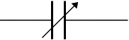
Variable capacitors are mostly used in radio tuning circuits and they are sometimes called 'tuning capacitors'. They have very small capacitance values, typically between 100pF and 500pF (100pF = 0.0001µF). The type illustrated usually has trimmers built in (for making small adjustments - see below) as well as the main variable capacitor.

Many variable capacitors have very short spindles which are not suitable for the standard knobs used for variable resistors and rotary switches. It would be wise to check that a suitable knob is available before ordering a variable capacitor.

Variable capacitors are not normally used in timing circuits because their capacitance is too small to be practical and the range of values available is very limited. Instead timing circuits use a fixed capacitor and a variable resistor if it is necessary to vary the time period.

Trimmer capacitors

Trimmer capacitors (trimmers) are miniature variable capacitors. They are designed to be mounted directly onto the circuit board and adjusted only when the circuit is built.

A small screwdriver or similar tool is required to adjust trimmers. The process of adjusting them requires patience because the presence of your hand and the tool will slightly change the capacitance of the circuit in the region of the trimmer!

Trimmer capacitors are only available with very small capacitances, normally less than 100pF. It is impossible to reduce their capacitance to zero, so they are usually specified by their minimum and maximum values, for example 2-10pF.

Trimmers are the capacitor equivalent of presets which are miniature variable resistors.

AC and DC

AC means Alternating Current and DC means Direct Current. AC and DC are also used when referring to voltages and electrical signals which are not currents! For example: a 12V AC power supply has an alternating voltage (which will make an alternating current flow). An electrical signal is a voltage or current which conveys information, usually it means a voltage. The term can be used for any voltage or current in a circuit.

Alternating Current (AC)

Alternating Current (AC) flows one way, then the other way, continually reversing direction.

An AC voltage is continually changing between positive (+) and negative (-).

The rate of changing direction is called the frequency of the AC and it is measured in hertz (Hz) which is the number of forwards-backwards cycles per second.

Mains electricity in the UK has a frequency of 50Hz.

See below for more details of signal properties.

An AC supply is suitable for powering some devices such as lamps and heaters but almost all electronic circuits require a steady DC supply (see below).


Direct Current (DC)

Direct Current (DC) always flows in the same direction, but it may increase and decrease.

A DC voltage is always positive (or always negative), but it may increase and decrease.

Electronic circuits normally require a steady DC supply which is constant at one value or a smooth DC supply which has a small variation called ripple.

Cells, batteries and regulated power supplies provide steady DC which is ideal for electronic circuits.

Power supplies contain a transformer which converts the ma

ins AC supply to a safe low voltage AC. Then the AC is converted to DC by a bridge rectifier but the output is varying DC which is unsuitable for electronic circuits.

Some power supplies include a capacitor to provide smooth DC which is suitable for less-sensitive electronic circuits, including most of the projects on this website.

Lamps, heaters and motors will work with any DC supply.

Please see the Power Supplies page for further information.

Power supplies are also covered by the Electronics in Meccano website