Read Important PC Repair Safety Tips. Manually testing a power supply involves working closely with high voltage electricity. Important: Do not skip this step! Safety should be your primary concern during a power supply test and there are several points you should be aware of before starting this process.
Open your case. In short, this involves turning off the computer, removing the power cable and unplugging anything else connecting to the outside of your computer. To make testing your power supply easier, you should also move your disconnected and open case somewhere easy to work like on a table or other flat, non-static surface.
Unplug the power connectors from each and every internal device. Tip: An easy way to confirm that each power connector is unplugged is to work from the bundle of power cables coming from the power supply inside the PC. Each group of wires should terminate to one or more power connectors. Note: There is no need to remove the actual power supply unit from the computer nor is there any reason to disconnect any data cables or other cables not originating from the power supply.
Group all of the power cables and connectors together for easy testing. As you're organizing the power cables, I highly recommend rerouting them and pulling them as far away from the computer case as possible. This will make it as easy as possible to test the power supply connections.
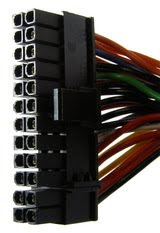
Short out pins 15 and 16 on the 24-pin motherboard power connector with a small piece of wire. You'll probably need to take a look at the ATX 24 pin 12V Power Supply Pinout table to determine the locations of these two pins.
Confirm that the power supply voltage switch located on the power supply is properly set for your country. Note: In the US, the voltage should be set to 110V/115V. Check the Foreign Electricity Guide for voltage settings in other countries.
Plug the PSU into a live outlet and flip the switch on the back of the power supply. Assuming that the power supply is at least minimally functional and that you've properly shorted the pins in Step 5, you should hear the fan begin to run. Important: Just because the fan is running does not mean that your power supply is supplying power to your devices properly. You'll need to continue testing to confirm that. Note: Some power supplies do not have a switch on the back of the unit. If the PSU you're testing does not, the fan should begin to run immediately after plugging the unit into the wall.
Turn on your multimeter and turn the dial to the VDC (Volts DC) setting. Note: If the multimeter you're using does not have an auto-ranging feature, set the range to 10.00V.
First we'll test the 24 pin motherboard power connector: Connect the negative probe on the multimeter (black) to any ground wired pin and connect the positive probe (red) to the first power line you want to test. The 24 pin main power connector has +3.3 VDC, +5 VDC, -5 VDC (optional), +12 VDC, and -12 VDC lines across multiple pins. You'll need to reference the ATX 24 pin 12V Power Supply Pinout for the locations of these pins. I recommend testing every pin on the 24 pin connector that carries a voltage. This will confirm that each line is supplying the proper voltage and that each pin is properly terminated.
Document the number that the multimeter shows for each voltage tested and confirm that the reported voltage is within approved tolerance. You can reference Power Supply Voltage Tolerances for a list of proper ranges for each voltage. Are any voltages outside the approved tolerance? If yes, replace the power supply. If all voltages are within tolerance, your power supply is not defective. Important: If your power supply passes your tests, I highly recommend you continue testing to confirm that it can operate properly under a load. If you're not interested in testing your PSU further, skip to Step 15.
Turn off the switch on the back of the power supply and unplug it from the wall.
Reconnect all of your internal devices to power. Also, don't forget to remove the short you created in Step 5 before plugging back in the 24 pin motherboard power connector. Note: The biggest mistake made at this point is forgetting to plug everything back in. Aside from the main power connector to the motherboard, don't forget to provide power to your hard drive(s), optical drive(s), and floppy drive. Some motherboards require an additional 4, 6, or 8 pin power connector and some video cards need dedicated power too.
Plug in your power supply, flip the switch on the back if you have one, and then turn on your computer as you normally do with the power switch on the front of the PC. Note: Yes, you'll be running your computer with the case cover removed which is perfectly safe as long as you're careful. Note: It's not common, but if your PC does not turn on with the cover removed, you may have to move the appropriate jumper on the motherboard to allow this. Your computer or motherboard manual should explain how to do this.
Repeat Step 9 and Step 10, testing and documenting the voltages for other power connectors like the 4 pin peripheral power connector, the 15 pin SATA power connector, and the 4 pin floppy power connector. Note: The pinouts necessary to test these power connectors with a multimeter can be found in my ATX Power Supply Pinout Tables list. Just as with the 24 pin motherboard power connector, if any voltages fall too far outside the listed voltage (see Power Supply Voltage Tolerances) you should replace the power supply.
Once your testing is complete, turn off and unplug the PC and then put the cover back on the case. Assuming your power supply tested good or you've replaced your power supply with a new one, you can now turn your computer back on and/or continue troubleshooting the problem you are having.


 Read Important PC Repair Safety Tips. Manually testing a power supply involves working closely with high voltage electricity. Important: Do not skip this step! Safety should be your primary concern during a power supply test and there are several points you should be aware of before starting this process.